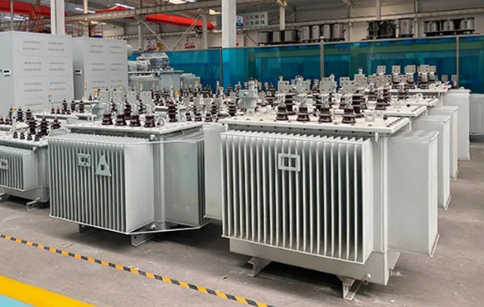
Iron core punching is one of the important parts of motor manufacturing. Punching manufacturing workload is the largest, the most stringent technical requirements, the highest requirements for the mold, is an important factor affecting economic benefits, so we must pay attention to the study of iron core punching manufacturing process and related mold structure issues. There are a variety of sizes on the chip, which can be classified as "internal size" and "matching size". Internal dimensions such as slot size, ventilation hole, marking slot and magnetic pole punching hole size, etc., generally use H10, higher accuracy level is not necessary, because after stamping, the error caused by inside and out is far greater than the error of the punching film itself. The "fit size" of the inner circle, the outer circle and the shaft hole matched with other parts, and the choice of accuracy level is related to the processing technology used. The precision of stator punching inside and outside diameter of small and medium-sized asynchronous motor is related to its loading mode. The inner diameter is generally H8, and the precision of the outer diameter is related to the process plan to ensure the coaxial degree of the stator. In the "optical outer circle" scheme, the punching outer diameter leaves a machining allowance of 0.5mm, and its accuracy is H8 or H9. The tolerance of the outer diameter of the "two not only" and "light stop" schemes is determined according to the accuracy of the punching and the iron core, because the outer diameter tends to increase after the iron core is pressed. Therefore, the upper limit value of the outer diameter tolerance of the punching plate is smaller than the upper limit value of the corresponding outer diameter of the iron core is 0.035 ~ 0.045mm (0.035mm for a small diameter), and the lower limit is generally determined according to the H7 tolerance. Table 1 lists the stator punching and core outer diameter tolerances of the JO2 series of externally pressed small asynchronous motors.
Stator punching is generally controlled within 0.05mm. For multiple punching individual parts (length of about 30mm) control within 0.12mm, but should be deburring treatment, treatment should be within 0.08mm. The rotor punching burr is controlled within 0.07mm, and individual slot parts are not allowed to be greater than 0.10mm. For the stamping after painting, the burr shall not be greater than 0.05mm. After punching, there will be different degrees of warping, the warping value of the single slot punching is larger, especially the rotor punching of the closed slot, after single slot punching, the warping is more serious, the punching outer diameter is less than 230mm is not allowed to exceed 2mm, 230mm is not allowed to exceed 3mm. The coaxiality of the inner circle or shaft hole and the outer circle is generally controlled within 0.04 ~ 0.06mm when the inner and outer circle is punched once, and the coaxiality should be appropriately relaxed when the inner and outer circle is punched twice. The uneven tooth distribution (or size teeth), that is, the difference between the maximum and minimum tooth width, should comply with the provisions of the drawings and relevant process documents, if there is no clear provision, you can refer to the level 3 or 4 accuracy test in Table 3. The center line of the groove should pass through the center of the circle, there should be no obvious skew phenomenon, and the axial holes (or outer diameters) of the positive and negative two pieces should be aligned when checking, and the distance between the two teeth should not be greater than 0.8mm after the end of the groove root is aligned. The insulation layer on the surface of the punching sheet should be thin and uniform, and have sufficient dielectric, oil resistance, moisture resistance and adhesion properties.
.png)